
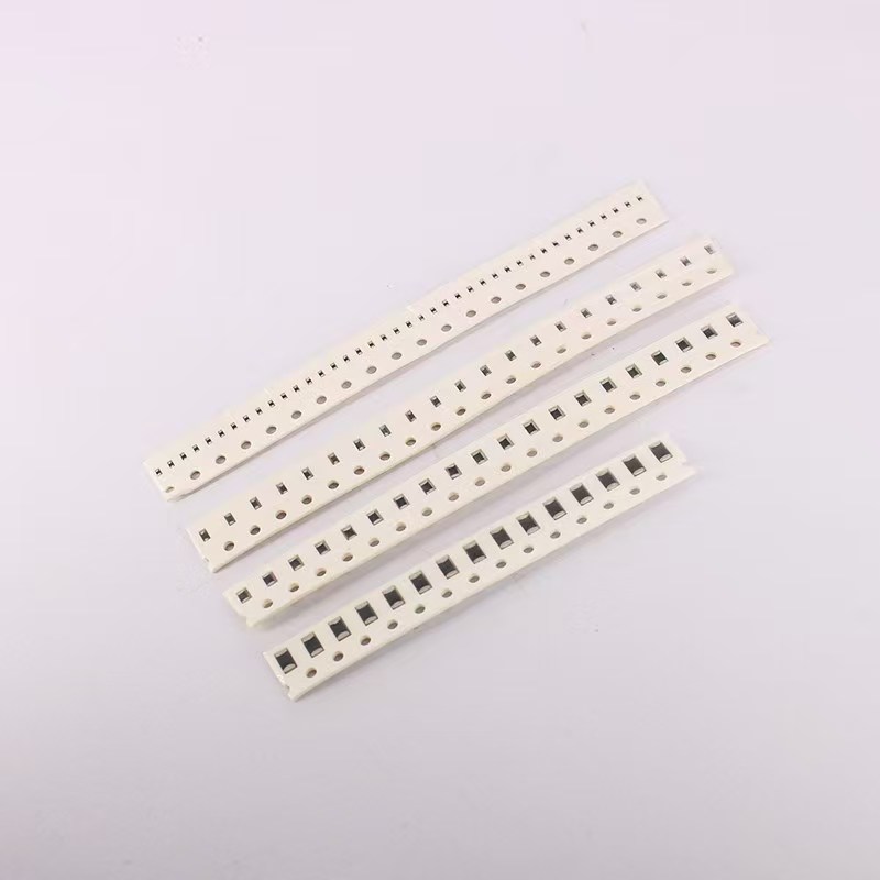
SMD NTC chip thermistors look simple, but several design choices affect accuracy, reliability, and manufacturability. The wrong case size can create PCB assembly problems, while the wrong soldering profile can shift the thermistor’s resistance.
This guide walks through the key selection steps for engineers specifying an SMD NTC chip thermistor.
What Is an SMD NTC Chip Thermistor?
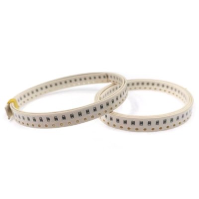
An SMD NTC chip thermistor is a surface-mount temperature sensor with a negative temperature coefficient. As temperature increases, its resistance decreases.
SMD NTC chips are used in:
- Battery pack temperature monitoring.
- PCB temperature compensation.
- Power supply protection.
- Consumer electronics.
- Automotive modules.
- Industrial controllers.
View our SMD chip NTC thermistors and general NTC thermistor chips for available configurations.
Step 1: Choose R25 and B Value
The two most important electrical parameters are R25 and B value.
R25
R25 is the resistance at 25°C. Common values include 10 kΩ, 47 kΩ, and 100 kΩ, but the correct value depends on the circuit design.
A lower resistance can reduce noise in some circuits, while a higher resistance can reduce self-heating when the thermistor is part of a voltage divider.
B Value
The B value describes how steeply resistance changes with temperature. Common B25/85 values include 3435 K, 3977 K, and 4250 K, but these are not universal.
The circuit should be matched to the thermistor’s R25 and B value. If you replace a part with a different B value, the temperature reading can shift even when R25 is the same.
Step 2: Choose the Case Size
SMD NTC chip thermistors are available in several standard case sizes. Smaller parts save board space, but they can be more sensitive to assembly stress.
| Case size | Typical trade-off |
|---|---|
| 0201 | Smallest footprint; best for dense boards; more sensitive to soldering and handling |
| 0402 | Good balance for compact consumer designs |
| 0603 | Common choice with easier placement and lower stress sensitivity |
| 0805 and larger | Larger thermal mass; easier handling; may respond more slowly |
The best choice is not always the smallest package. If the thermistor must measure a specific surface or point temperature, larger thermal mass may reduce response speed or change thermal coupling.
Review our SMD chip NTC thermistors for available case sizes.
Step 3: Match Tolerance to Accuracy Requirements
NTC tolerance is usually expressed as a resistance tolerance, such as ±1%, ±2%, ±3%, or ±5%.
Resistance tolerance does not translate directly into temperature accuracy. The resulting temperature error depends on the B value and the slope of the resistance-temperature curve.
For high-accuracy temperature measurement, select a tighter resistance tolerance and a well-controlled B value. For simple over-temperature protection or coarse compensation, a wider tolerance may be acceptable.
If the application requires a more stable sealed sensing element instead of an open chip, compare the design with our glass encapsulated NTC thermistors.
Step 4: Design the Soldering Profile Carefully
SMD NTC chips are sensitive to thermal and mechanical stress during soldering.
Reflow Soldering
Use a reflow profile recommended by the supplier. Key points include:
- Limit peak temperature.
- Control time above liquidus.
- Avoid excessive temperature gradient.
- Confirm the maximum rated soldering temperature.
Thermal Shock
Do not expose the chip to a sudden temperature change immediately after soldering. Allow the board to cool gradually according to the recommended process.
Board Flexing and Placement
Avoid placing the thermistor in a high-flex area of the PCB. Mechanical stress can crack the chip or shift its resistance.
Solder Pad Design
Use the recommended land pattern for the case size. A pad that is too large or too small can cause tombstoning, poor solder fillets, or uneven thermal stress.
If you need support on chip handling and manufacturing, see our article on NTC thermistor chips in modern electronics.
Step 5: Consider PCB Layout and Thermal Coupling
An SMD NTC thermistor measures the temperature of the area where it is mounted. PCB copper, nearby components, and airflow all affect the reading.
Follow these layout principles:
- Place the thermistor close to the heat source or battery cell being monitored.
- Avoid placing it near large components that block airflow.
- Minimize copper thermal mass if a fast response is required.
- Keep the sensing area isolated from unrelated heat sources.
Step 6: Specify Tape and Reel for Automated Assembly
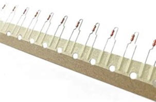
For volume production, specify the correct packaging format:
- Tape width.
- Pocket size and pitch.
- Reel quantity.
- Polarity or orientation requirements.
- Moisture sensitivity level and storage conditions.
For automated assembly support, see our article on NTC thermistor carrier paper tape for automated electronics manufacturing. You can also review our NTC thermistor carrier paper tape product page.
SMD NTC Chip Selection Checklist
Before requesting a quote, prepare these details:
- R25 value.
- B25/85 or B25/50 value.
- Resistance tolerance.
- Required temperature accuracy.
- Case size.
- Operating temperature range.
- Reflow or soldering process.
- PCB location and thermal environment.
- Tape and reel requirements.
- Target annual volume.
How HORLE Supports SMD NTC Chip Selection
HORLE supplies NTC chips, lead wires, housings, and sensor assembly materials from one manufacturing system. That helps engineers match the chip, packaging, and soldering process instead of qualifying separate suppliers.
Learn more about our production approach in our article on the complete manufacturing process of high-quality NTC thermistors.
If you also need leaded NTC thermistors, review our guide on how to choose the right wire material for lead wires.
Frequently Asked Questions
Is a smaller SMD NTC chip always better?
No. Smaller parts save space but may be more sensitive to soldering and mechanical stress. The case size should match the board layout, response requirement, and assembly capability.
Can I replace an SMD NTC chip with the same R25 but a different B value?
Not without checking the circuit. A different B value changes the resistance-temperature curve and can shift the temperature reading even if R25 is identical.
How does resistance tolerance affect temperature accuracy?
Resistance tolerance and temperature accuracy are related but not identical. The temperature error also depends on the B value and the slope of the NTC curve.
Can I hand-solder an SMD NTC chip?
Hand soldering is possible for prototyping, but it should follow controlled temperature and time limits. For production, use the supplier’s recommended reflow profile.
What packaging should I specify for automated assembly?
Specify tape width, pocket size, pitch, reel quantity, orientation, and any moisture sensitivity or storage requirements.
Next Step
Start with R25, B value, tolerance, and case size. Then confirm the soldering profile and PCB location before finalizing the part number.
Review our SMD chip NTC thermistors, NTC thermistor chips, or the full HORLE product range to begin your selection.